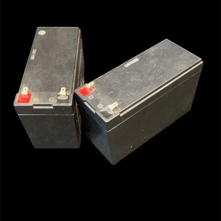
Description
kit contains
1 rf complaint voltage regulator with adjustment
1 multi meter for battery measurements
24v wiring harness
1 spare 12v battery charger smart charger
1 testing tag
how to use
- place the colored and labelled link wire between the positive (red) of one battery and the negative (black) of another
- use the multi meter to measure the voltage on the two remaining contacts that have no cable attached. You should read a voltage of around 24v
- connect the bootlace connectors cables (look like the plastic bit of a shoes lace but metal and blue plastic) into the clips which previously were connected to the 12v battery pack red to red and black to black
- make sure the knob on the regulator is set to its lowest setting (see dial indicator) on the case
- place this regulator module in the waterproof housing
- connect the ring bolt terminals on the regulator to these remaining contacts you have just measured on the batteries red to red and black to blacktesting
- adjust the knob until the Amps A on the PIT reader reads 0.75A
- take the tag to do a range test looking for circa 1m +/-8% from the top of the white pipe taken from the center of the antenna.
- If the read range is too low increase the current slightly by further adjusting the knob but do not let it exceed 1.1A!!
- do this in small steps and repeat until you get a good read range at a safe current consumption (A)
- the lower the current the better as you will reach a point where the current will increase but will not drastically change the read range
- NOTE on checking the voltage of the battery pack, it is now wired into a 24v configuration. A low/ dead battery now being 22v as opposed to 11v
- to take them all apart disconnect the power to the reader then remove the cables sequentially in the reverse of the way outlined in these instructions


